
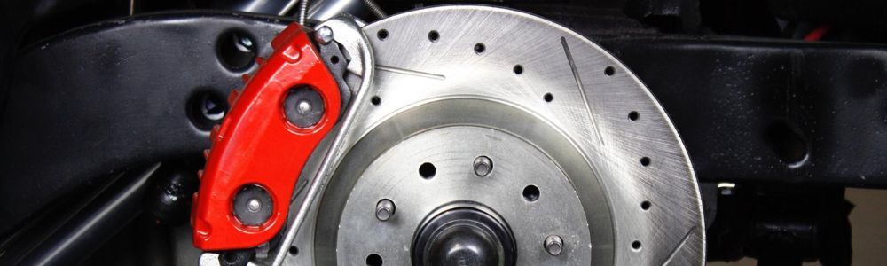
If you are driving a classic GM or Mopar with factory drum brakes, upgrading to disc brakes is one of the best things you can do for safety and driveability. Disc brake conversion kits are designed to bolt up with standard hand tools. You can view all 4-wheel, Front, and Rear Disc Brake Conversion kit options here !
Before you get started, trial fit all components and check your rim clearance. These kits are designed to run with 15 inch or larger wheels. 14 inch wheels are not supported. Do not modify, paint, or powder coat any part of the kit until you have confirmed fitment. Modified or painted parts are not returnable.
This is a universal front and rear conversion walkthrough, covering GM A/F/X Body, Full Size Chevy, and Mopar applications. Common steps shared across all the guides (spring removal, bearing packing, caliper mounting, bleeding order) are written as the core process. Application specific differences, like the Mopar adjustable proportioning valve, staggered shock caliper orientation, C-clip vs drop-out axle procedures can be found in the correct installation PDF for your Disc Brake Conversion Kit, downloadable below! We always recommend having the brake kit installed by professionals.
Tools You Will Need
- Ball joint fork
- Spring compressor (highly recommended for coil spring vehicles)
- Drum brake tool (optional, helps with removal)
- Standard hand tools

Part 1: Front Disc Conversion
Step 1: Get the Car Ready
Support the car securely on jack stands. Chock the rear wheels and set the parking brake so the car does not roll. Always work on a flat, level surface. Pull the wheels off to get access to the brake system.
Step 2: Disconnect the Tie Rod Ends
Remove the cotter pin and castle nut that holds the tie rod to the steering arm. You will reuse those castle nuts later, so set them aside. Use a heavy hammer to knock the tie rod end loose from the steering arm. A pickle fork can help if things are stubborn.
Step 3: Disconnect the Front Flex Hoses
Unscrew the hard line from the flex hose. Be careful not to get brake fluid on any painted surfaces. Remove the flex hose retaining clip and pull the hose out of the frame mounted bracket.
Step 4: Remove the Old Drum Brake Assemblies
This is where the spring compressor earns its keep. The coil springs on these cars carry a lot of tension and can cause serious injury if handled improperly. Do not skip the spring compressor.
The preferred method:
- Remove the shock absorber
- Install the spring compressor and follow the tool's directions
- Compress the spring until all pressure is released from the control arm
- Remove the cotter pin and castle nut from the upper ball joint, and keep the nut for reuse
- Use the pickle fork to release the upper ball joint from the spindle
- Raise the upper control arm out of the way
- Repeat the same process to release the lower ball joint and remove the spindle assembly
If you have a sway bar, removing the sway bar link at this point gives you a lot more room to work.
Step 5: Inspect the Suspension While You Are In There
Now is a good time to go through the suspension before you button everything back up. Check the inner and outer tie rod ends and ball joints for wear. Look at the rubber boots for cracks or tears. Also check sway bar links and bushings. If anything needs attention, this is the right time to address it.
Step 6: Remove the Original Steering Arms
Pull the dust cap, cotter pin, and washer off the old spindles. Remove the hub and brake shoes so you can get to the steering arm bolts. Unbolt the steering arm and set it aside for reuse. Your conversion kit includes new hardware for reinstallation.
A note on older cars: some early steering arms used smaller bolt holes that will need to be drilled out to accept the new 1/2 inch bolts. If you are not comfortable drilling the arms, replacement arms are available.
Step 7: Install the New Disc Brake Spindles
Set the new spindle on the lower ball joint and attach it with the original castle nut. Torque to spec per your factory assembly manual and lock it in place with the new cotter pin included in your kit.
Both spindles in your kit are identical. There is no left or right, so do not worry about getting them mixed up.
Pull the upper control arm down, insert the upper ball joint, and attach it with the original castle nut. Most upper ball joints torque to 40 to 60 ft/lbs. Lock it in place with the new cotter pin.
Step 8: Release the Spring
You can now slowly release the spring compressor. Once the spring pressure is off, reinstall the shock absorber.
Step 9: Install the Caliper Brackets, Backing Plates, and Steering Arms
Slide the caliper bracket onto the spindle. Place the spindle gasket in position, then set the backing plate over the caliper bracket. Fasten everything down with the 5/8 inch bolt supplied with your kit, then bend the tabs down against the bolt head to lock it in place.
The caliper bracket opening should face toward the rear of the car. Left is the driver's side, right is the passenger's side.
Reinstall the original steering arm using the new bolts from your kit. Put the tie rod end back into the steering arm, fasten it with the original castle nut, torque to spec, and lock it with the new cotter pin. If you removed the sway bar link earlier, now is a good time to put it back.
Step 10: Pack the Bearings and Install the Rotors
The bearing races come pre-installed in the rotors. If your bearing kit came with extra races, set them aside. Before installing the bearings, inspect the bearing area of the rotor for any casting sand or debris.
Start with the rotor face down. Apply a little bearing grease to the race and pack the larger inner bearing with grease. Drop it into the rotor and place the grease seal on top. Tap the seal in carefully. A small block of wood placed over the seal works great here to protect the rubber from damage.
Flip the rotor face up, grease the outer race, and pack the smaller outer bearing. Slide the rotor onto the spindle, being careful not to let the outer bearing fall out. Install the keyed washer and castle nut, tighten until the bearings seat, then back the nut off until the rotor spins freely. Lock it with a new cotter pin and install the dust cap with a mallet and a large socket. A screwdriver along the edge works too.
Step 11: Mount the Calipers and Flex Hoses
Your new calipers come fully loaded with pads, pins, bolts, and copper washers. Start by removing the caliper pins. Position the caliper in the bracket with the bleeder screw at the 12 o'clock position. If it will not go in with the bleeder pointed up, you have the wrong side. Swap it and try again. Once positioned, insert the caliper pins and torque to approximately 50 ft/lbs.
Important: The bleeder screws must point up. If they point down, air gets trapped in the caliper and the system will not bleed properly.
To install the flex hose, remove the banjo bolt and copper washers from the caliper. Place one copper washer on top of the hose fitting and insert the banjo bolt through it. Place the second copper washer on the bottom of the fitting and tighten the banjo bolt to approximately 40 to 50 ft/lbs. Make sure the hose seats square against the caliper.
Route the other end of the flex hose into the original frame bracket. You may need to file the inside of the bracket slightly to get the new hose to fit. Push on the new clip from your kit to secure it.
The hose may seem a little tight when you turn the wheel from lock to lock. This is normal. The suspension is at the absolute limit of its travel in that position. It is not a situation you would ever reach during normal driving.
Part 2: Upper Assembly (Master Cylinder and Booster)
Step 1: Remove the Old Master Cylinder
Remove the brake lines from the master cylinder carefully so you do not get fluid on any painted surfaces. Disconnect the clevis from the pedal rod under the dash. If your car was originally a power brake car, pull the booster mounting nuts from the firewall and remove the booster and master as a unit. If it was a manual brake car, just remove the master cylinder mounting nuts and pull the master off.
Step 2: Mount the New Master Cylinder and Booster
For power brake conversions: Bolt the booster brackets to the booster and mount the booster to the firewall studs. On some applications the booster sits tilted up at around 30 degrees. That is normal.
Before placing the master onto the booster, check the booster rod length against the pocket depth in the master cylinder. The rod should protrude from the face of the booster roughly the same length as the pocket is deep. Short systems use about a 1/4 inch rod and pocket. Long systems use about a 1 1/2 inch rod and pocket. Some Delco style boosters come with both a long and short rod. Use the short one if your master has a shallow pocket, and the long rod if the pocket is over an inch deep.
When you place the master cylinder against the booster face, it should slide on without any resistance. If you feel resistance, either the rod is too long or there is a plug in the back of the master that needs to be removed.
Slide the valve bracket over the booster stud and loosely tighten it. Leave it a little loose for now. It makes running the brake lines much easier. Bolt the proportioning valve to the bracket with the hardware from your kit.
For manual brake conversions: Place the master cylinder over the firewall studs and hold it with a nut on the passenger's side stud. Slide the valve bracket over the driver's side stud and leave it loose for now. Mount the proportioning valve to the bracket, then run the brake lines. Tighten everything down once the lines are in place.
Step 3: Install the Brake Lines
If you purchased a line kit, the two smaller lines go to the master cylinder. Run them into position and tighten them up once the master and bracket are in place.
Step 4: Install and Adjust the Pedal Rod
Hold the brake pedal about 1/8 inch down from its stop. Adjust the pedal rod so that when it is connected, the pedal sits at that same 1/8 inch position. The kit may include an extension rod if you need to make up distance. Tighten all jam nuts on the rod after making your adjustments to lock everything in place.
The pedal rod should not be in a bind when you connect it to the pedal arm. If your pedal only has one hole, you may need to drill a second hole about 1 inch lower than the original. Let the rod and clevis show you where it wants to go before drilling.
For power brake setups: Connect a vacuum line from the intake manifold or carburetor to the booster check valve. You want at least 14 in/hg of vacuum at idle, with 16 to 18 in/hg being ideal. If your engine does not make enough vacuum, the booster will not work properly.
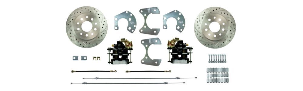
Part 3: Rear Disc Conversion (If Applicable)
Step 1: Get the Car Ready
Support the car on jack stands and chock the front wheels. Remove the rear wheels to access the drum brakes.
Step 2: Remove the Old Rear Drum Brakes
C-clip axles: Open the rear housing cover and remove the C-clips before pulling the axles. After the axles are out, unbolt the drum brake assembly and remove it as a complete unit. You do not need to remove the shoes and hardware separately. Clean the front and back of the axle flange with steel wool or a wire brush to prep it for the new caliper brackets.
Drop-out axles: Unbolt the axle flange from the housing and pull the axle out. Remove the drum assembly and clean the flange the same way.
Step 3: Install the Dust Shields (Optional)
If you are using the included dust shields, install them on the front of the axle flange before reinstalling the axles. The caliper opening should be at the 2 o'clock position on the driver's side and 10 o'clock on the passenger's side. They will get bolted in place when you mount the caliper bracket in a later step.
Staggered shock owners: The driver's side shield mounts toward the front of the car. The passenger's side still mounts toward the rear.
Step 4: Reinstall the Axles
C-clip axles: Push the axles back in and reinstall the C-clips. Replace the housing gasket and reinstall the cover.
Drop-out axles: Install the included flange spacer on the axle to fill the space the old drum backing plate was occupying. Slide the axle back in. Do not use the spacer if you are running the optional dust shields, as the shields are already welded into the backing plates.
Step 5: Install the New Caliper Brackets
The caliper brackets mount to the inboard side of the axle flange. The machined surface faces the flange. The caliper opening should face the rear of the car. Place the 1/4 inch spacer between the bracket and the flange, then bolt everything together with the supplied hardware.
Step 6: Install the Rotors
Clean the hub with steel wool or a wire brush before sliding the rotor over the studs. Snug it down with two or three lug nuts. If the rotor's center hole is too small to slide over the hub, you will need to open it up with a die grinder or have a machine shop take care of it.
Step 7: Install and Center the Calipers
Position the caliper in the bracket and install the mounting pins. The parking brake assembly should be on top with the bleeder pointing toward the front of the car. If the pads do not clear the rotor, adjust the caliper position using the included spacers. Add spacers between the flange and bracket if the inside pad is rubbing. Remove spacers if the outside pad is rubbing. You can stack the spacers to get the right thickness.
Step 8: Attach the Flex Hoses
Same process as the front. Copper washer on top, banjo bolt through the fitting, second copper washer on the bottom, tighten to spec.
Step 9: Install and Adjust the Emergency Brake Cables
If your kit includes new rear emergency brake cables. You will use your existing intermediate and front cables. Run the cable up through the center of the spring and insert the metal end securely into the notch on the emergency brake lever. No clip is needed to hold it to the caliper. Connect the other end to the existing intermediate cable using the supplied hardware. After the cables are connected, engage and release the emergency brake lever several times to activate the self-adjustment mechanism in the calipers. Keep at it until the brake is fully engaged and the rear wheels will not turn by hand. Make a point to use the emergency brake regularly going forward to keep the adjustment dialed in. This must happen before adding brake fluid into the system.
Step 10: Install the Flex Hose Mounting Tabs
The flex hose mounting tabs need to be tack welded to the rear axle housing where your hard lines end. Before you do that, you will need to shorten your existing rear axle hard lines to compensate for the flex hose connection at the caliper. A good rule of thumb is that your lines will end up about 6 to 8 inches shorter than the factory lines. Once the tabs are welded, insert the flex hose into the bracket and secure it with the clip provided. Then thread the hard line into the end of the flex hose and tighten with a wrench.
Bleeding the System
Before bleeding, make sure the emergency brake is properly adjusted if you have a rear disc kit installed.
Work from the wheel farthest from the master cylinder forward. The correct bleeding order is:
- Right Rear
- Left Rear
- Right Front
- Left Front
If you are concerned about DOT 3 fluid damaging painted or rubber components, synthetic DOT 5 is a good alternative. If you end up with a spongy pedal after bleeding, double check that all bleeder screws are pointing up. Calipers with bleeders that are pointed down will trap air and the system will not bleed out fully. On rear disc setups, the bleeders should be positioned horizontally. You can remove the caliper mounting pins and rotate the caliper to get the bleeder in the right position. Just keep the pads over the rotor when you do this.
Proportioning Valve Adjustment (Mopar Applications)
Mopar conversion kits come with an adjustable proportioning valve rather than a fixed combination valve. After bleeding the system, open the valve all the way by turning it counterclockwise as far as it will go. Then do a few test panic stops in a safe open area like an empty parking lot. If the rear brakes do not lock up, you are good to go. If they do lock up, turn the valve clockwise to reduce rear brake pressure and test again. Continue until the rear wheels stay under control during a hard stop.
A Note on Wheel Fitment
These kits will push your wheels out approximately 1/8 inch per side. In some cases on rear axle conversions, you may need longer wheel studs after installation. Always confirm clearance before driving.
Quick Reference Torque Guide
- Upper and lower ball joints: 40 to 60 ft/lbs (check factory spec for your application)
- Caliper bracket bolts (Mopar spindle assembly): 95 ft/lbs
- Caliper pins: approximately 50 ft/lbs
- Banjo bolt at caliper: approximately 40 to 50 ft/lbs
- Mopar rear axle flange bracket (T-bolt): 55 ft/lbs
Always verify torque values against your factory assembly manual for your specific vehicle.
Installation Guide Reference
| Part Number | Description | Instructions |
|---|---|---|
| General Motors | ||
| AFXDC01C | '64-'72 A Body Power Front Conversion | Download |
| AFXDC02C | '67-'69 F Body Power Front Conversion | Download |
| AFXDC03C | '62-'67 X Body Power Front Conversion | Download |
| AFXDC04C | '68-'74 X Body Power Front Conversion | Download |
| AFXRD01 | 10/12 Bolt GM Non-Staggered Rear Disc Conversion | Download |
| AFXRD01N | 10/12 Bolt GM Non-Staggered Rear Disc Conversion | Download |
| AFXRD05 | 10/12 Bolt GM Staggered Rear Disc Conversion | Download |
| AFXSD01C | '64-'72 A Body Non-Power Front Conversion | Download |
| AFXSD02C | '67-'69 F Body Non-Power Front Conversion | Download |
| AFXSD03C | '62-'67 X Body Non-Power Front Conversion | Download |
| AFXSD04C | '68-'74 X Body Non-Power Front Conversion | Download |
| FSC55DCC | '55-'57 Full Size Chevy Power Front | Download |
| FSC58DCC | '58-'64 Full Size Chevy Power Front | Download |
| FSC55SDC | '55-'64 Full Size Chevy Non-Power Front | Download |
| FSC65SDC | '65-'68 Full Size Chevy Non-Power Front | Download |
| FSCRD01 | Drop Out Large Axle Rear Disc Conversion | Download |
| Chrysler / Dodge | ||
| MDC62DC | '62-'72 B Body Power Front Conversion | Download |
| MDC66DC | '60-'76 A Body Power Front Conversion | Download |
| MDC62SD | '62-'72 B Body Non-Power Front Conversion | Download |
| MDC66SD | '60-'76 A Body Non-Power Front Conversion | Download |
| MDCRD01 | Rear Disc Conversion | Download |